How Torque Sensor Measurements Are Used in Automotive Applications
Industry Insights
How Torque Sensor Measurements Are Used in Automotive Applications

Torque sensors have been used in numerous applications throughout the automotive industry. Rotary torque sensors are used for strain measurement, testing of clutch and gearboxes, and dynamic torque within the engine. Additionally, powertrain, brake, and suspension systems are tested using torque sensors, which are also used to measure horsepower in the interest of improving fuel efficiency.
Many automotive manufacturers use in-vehicle torque sensors for mapping engine torque and calibrating the automatic transmission. Moreover, torque sensors are used in fleet and customer-use testing so engineers can collect data under ordinary (or extraordinary – in the event of an accident) conditions.
Challenges of Measuring Torque in Automotive Applications
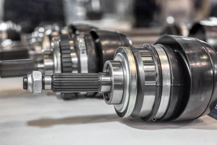
CV shaft torque sensor measurements present many challenges.
Another challenging application of torque measurement in the automotive industry is the measurement of torque in CV (constant velocity) joints. The CV joint allows a driveshaft to transmit power at constant rotational speed through a variable angle without too much friction increase. But these torque measurements can be difficult to make due to space constraints. Manufacturers have ways of getting around this however.
Inline and Reaction Torque Sensors
Whether you’re measuring static or dynamic torque, you will use either inline or reaction torque sensors. Inline torque sensors are made by the insertion of a torque sensor between two torque-carrying components. The process is similar to inserting an extension between a socket wrench and a socket. With inline torque measurement, the torque sensor can be placed as near as possible to the torque being measured, helping avoid measurement errors like extraneous loads or “parasitic” torques from bearings, for example.
Reaction torque sensors are based on Newton’s third law (For every action, there is an equal and opposite reaction). Say you wanted to measure torque produced by a motor. One way to do this is to measure the torque necessary to prevent the motor from turning – the reaction torque. Whether you’re measuring inline or reaction torque, you have to get the information picked up by the torque sensors to your display electronics so you can interpret the measurements.
Static and Dynamic Torque
There are two basic categories of torque: static and dynamic. The difference between static and dynamic forces is that dynamic forces involve acceleration, while static forces do not. Indeed, dynamic force is related to acceleration by Newton’s second law: Force = Mass × Acceleration
An example of static torque would be torque produced by a clock spring to move a second hand. If a car is moving at steady speed, it demonstrates rotating static torque, since there is rotation, but no acceleration. Car engines produce both static and dynamic torque. For example, if you measure torque in a car’s crankshaft, you’re measuring dynamic torque because acceleration is involved in cylinders firing and pistons rotating the crankshaft.
An example of static torque in an automobile would be the opening and closing of old-fashioned crank windows. Yes, there is rotational acceleration, but the dynamic torque is negligible in comparison to the frictional forces that move the window up or down.
Slip Rings vs. Rotary Transformer Systems
With inline torque measurements, rotating slip rings are economical and usable in many applications for sending information picked up by the sensor to a display readout. They are the most commonly used technique to connect rotating sensors and stationary electronics. A set of conductive rings rotate with the sensor, while a series of brushes contact the rings and transmit the signals to the electronic readout. The main drawback to slip rings is that the brushes (and to some extent the rings themselves) wear out, so they’re not great for long term tests.
The rotary transformer system uses a rotary transformer coupling to transfer power to a rotating sensor. An external instrument delivers AC excitation voltage to a strain gage bridge through an excitation transformer. The strain gage bridge drives a second rotary transformer coil to obtain the torque signal from the rotating sensor. Because there aren’t any brushes or rings, wear isn’t a problem, and this system can be used in long-term testing applications.
Calibration to Ensure Accuracy of Torque Measurements
With any measurement sensor, proper calibration is necessary to ensure they work properly and that their measurements are accurate. Calibration is done by comparing a known standard signal to the sensor’s signal. Torque sensors are typically calibrated once a year. Accuracy of torque sensor measurements is absolutely essential. Sometimes custom torque sensors are incorporated into custom mechanical packages, and accuracy must be assured before the user can be confident of measurements made with it.
When You Need Custom Torque Measuring Devices
When you need help in the development of a custom torque sensor or looking to calibrate a torque sensor, it’s important to work with a provider that can deliver the customization you need. Sensing Systems has extensive experience in both the manufacturing and the calibration of custom torque sensors to meet unique customer needs. If you are interested in learning more about our capabilities, please contact one of our specialists. We would be happy to answer your questions and help you obtain the exact torque sensor you need for your automotive application.
Industry Insights
The Role of Load Cells in Safety-Critical Applications
Industry InsightsThe Role of Load Cells in Safety-Critical Applications ...
Load Cells for Robotics and Automation: Enabling Precision and Control in Robotic Systems
Industry InsightsEnabling Precision and Control in Robotic SystemsIn the...
INDUSTRIAL BOLTING
Background: A Bolted Joint is the most widely used method for fastening...


